Benco Products Inc - Parts and Service for planters and sprayers

 605.213.1010

Installing Liquid on a Planter

Case 2150 with Liquid Handling from Benco Products.

Yes, you CAN install liquid on your planter.

Installing liquid on a planter is a big job. But it isn’t difficult. 

Follow these simple steps to achieve a professional quality installation on any planter. Every planter is different, but the steps you take are the same. The goal of this tutorial is to help you understand the complete process and to give you a few tips and tricks, not to give you a precise set of instructions.  

Contact BENCO Products if you need extra parts or run into problems. If you live near the southeast South Dakota area, we can also install everything for you.  Just let us know how we can help. 

Step 1: Mount your tank

Mounting your tank is the first step in adding liquid to your planter. This gives a point of origin for which many of the other decisions are based.

  1. Mount your tank riser mounts to the planter 
    The first thing we have to do is get the tank up and out of the way so it doesn’t interfere with other components when the planter is folded. That is the job of the tank riser mounts.

    They are shaped like a T. The base plate is slightly wider than the center beam with a vertical beam to give the tank clearance for everything mounted on the tool bars. If your tank sits perpendicular to the center bar, the tank cradle will probably bolt directly to the risers. If it sits parallel, you will probably need to add support rails. 

    BENCO often engineers pump mounting bolts into the base plate to make it easy to mount your hydraulic pump.

    • Big threaded U-bolts secure the tank risers to the center beam without adding much width to the beam itself.
    • The threaded U-bolts go around the center beam and up through the holes in the riser base plate sitting on top of the bar. Secure with washer, lock washer and nut.
    • Don’t tighten it too much yet, you will need to be able to move it around a bit when you mount the support rails. In fact, tightening all nuts is the absolute last step in mounting your tank.


  2. Mount the support rails to the risers (if necessary).
    Now that we have the height, we need to match the tank skid’s mounting points.These beams bolt directly to the risers and the tank skid. Bolt them loosely, but securely, to the risers (finger tight). You may need a little wiggle room when adding the skid.

    This step may or may not be necessary depending on if the tank is parallel or perpendicular to the center beam. John Deere planters often need them, Case often do not. 

  3. Mount the tank skid.
    This is where the heavy machinery comes in. Use a forklift, hoist, or other machinery to lift the tank skid up onto the support rails. Bolt the skid to the rails.


  4. Mount the tank
    You will probably want to use machinery for this as well. Drop the tank into the skid and make sure the holes in the bottom of the tank are centered in the access hole at the bottom of the skid. The better the tank is positioned, the better it will drain.


  5. Finalize the position on the planter.
    Now that we have the completed tank loosely mounted to the planter, it’s time to check for clearance and access. Make sure you like where the everything is positioned and that you have access to everything. Close the planter to check for clearances. You should be able to nudge it back and forth along the center bar to reposition the tank if the U-bolts are still loose.


  6. Strap down the tank.
    Once you  are happy with the position, strap down your tank.

    • Tank straps are commonly either steel or thick nylon straps. Either way, they bolt to the skid with long bolts that give you lots of adjustment. Tighten all four corners until the straps are snug and the tank is properly seated in its skid, but not tight.

    • Be aware that often tanks can rotate slightly as you tighten them down. If possible, have someone watch the tank as you tighten the straps to make sure it doesn’t move on you.

    • Make sure the tank hasn’t rotated out of position and then do the final tightening on the straps. The tank should squish down slightly into its cradle when it is properly secured.


  7. Tighten your bolts.
    Take one quick final look at the tank’s position on the planter. If you are still satisfied, tighten all the bolts on the brackets. Your tank is mounted!


  8. Install your tank valves & fittings.
    Now that the tank is secure, it is a great time to install the plumbing underneath.

    Input (from quick-fill)
    We usually run 2″ hose and fittings for the quick-fill line. You will need an adapter from the tank, a 2″ hand valve, and a 2″ barbed elbow fitting to attach your quick-fill hose.

    Mount your fittings to the tank an adapt it down to the correct size. Next comes the 2″ on/off valve. This not only makes maintenance easier, it also relieves pressure on the rest of the system when the tank is full during transport or storage. The last piece is a 2″ barbed elbow fitting to attach your hose to. This allows us to perfectly line-up to the quick fill hose while keeping it straight. 

    Output (to pump) 
    For hydraulic pumps, we use 1.25″ line to make sure the pump is always flooded. For 12V pumps, you can get by with a 1″ or 0.75″ line. You will need another hand valve, a filter screen, an adapter for the tank, and 2 elbow fittings. 

    Mount your adapter to your tank seal. We usually will then run our first elbow to keep the tank plumbing out of the way of the quick-fill hose. Mount your hand valve, then your filter screen. You’ll need to clean out the filter regularly, so make sure you have easy access to take off the filter housing. 

    NOTE: If you are using a hydraulic centrifugal pump, you will move the filter AFTER the pump.  If the filter clogs and starves the pump, it will ruin the ceramic pump seals in just two revolutions, causing leaks.  

    Finally, add your barbed elbow that your pump hose will attach to. If your pump is mounted close the the tank, you may need to make a longer loop around and back to the pump to ensure a smooth flow of liquid. This may mean the elbow would seemingly point in the wrong direction.  

Step 2: Mount your pump

Now that you have your tank securely mounted to the planter, you can mount the pump. It doesn’t matter if you are using a 12V pump or a standard hydraulic pump. 

Find a location that works .
Pumps can go almost anywhere. Find a place where it fits and allows easy access to plumbing and power/hydraulics. 

We like to mount it on the center bar right by the tank (often under it if there is room). This makes plumbing much easier and keeps it out of the way. We like doing this so much that we often engineer the pump mounting bolts into the base plate of the tank riser mount, but a big U-bolt works the same.

If you are using U-bolts to secure the pump to a bar, leave them loose enough so you can move it back and forth to find the perfect position.  There will be a fair amount of bulky plumbing (especially on hydraulic pumps), so make sure you have enough room for fittings and hoses to clear surrounding items. 

When you are happy, tighten the bolts to lock it down.
We’ll run the plumbing in a later step.

Step 3: Mount your quick-fill valve

The quick fill coupling is usually a 2″ Banjo cam lock valve mounted on the planter with a bracket. This will allow you to quickly and easily fill or drain your main tank. 

  1. Find a location that works.
    This is a convenience feature, so make sure you mount this in an easily accessible area. We like to mount it as far back on the planter as possible. Our favorite spot is on the side of the back steps, but that doesn’t work for every planter. Just make sure it’s easy to get to with a long bulky hose.


  2. Bolt the bracket to the mounting point.
    Bolt the bracket to the planter. You will likely need to drill at least one hole.


  3. Mount the quick-fill valve
    We will mount the valve to the bracket using two of the built-in bolts on the valve.

    • Unbolt two nuts on the valve. These are usually the ones on the opposite side of the valve handle.

    • Insert the exposed bolts into the holes on the bracket and reattach the nuts.

    • Test the valve handle. Be sure the valve is secure and the handle has the full range of motion without obstruction from surrounding parts of the planter. 

Step 4: Add a Dosatron injection pump (optional)

This step is completely optional, but Dosatrons are extremely popular and worth including in this discussion. 

Dosatrons typically come with a tank and stand, making mounting easy. Just bolt the tank stand to the planter and plumb it in. The Dosatron will be fed directly by the pump and then run out to your OnSite FMS system where the treated liquid is divided out to the row units.  

Find a location that works for you.
You’ll need access to easily fill the tank from the top, adjust the valves,  and change the injection rates on the Dosatron itself. It also needs to be up out of the way as planter runs.

We like to mount them on the steps or the platform up by the seed tanks, but the mounting point is up to you. Remember it will be plumbed in between the pump and OnSite’s manifold. If you can mount it close to the rear of the planter it will make plumbing much easier later.   

Bolt the Dosatron to the mounting point.
Once you find the perfect spot, bolt the stand to the planter. You will likely have to drill at least one hole.  

Step 5: Add OnSite FMS monitoring (or red balls)

OnSite FMS’ FlowBoards have integrated manifolds that will split your liquid out for each row unit. The same is true for red ball systems. We will just give a general overview of how to install OnSite FMS or red balls. We recommend going to OnSiteFMS.com/onsite-installation for detailed installation details. 

If you are adding red balls, the steps are the same, you just won’t have to wire anything in at the end. 

Find a location that works and mount your bracket.
You will mount your FlowBoards to the toolbar with U-bolts and a simple bracket. Find a spot that you can mount the bracket to the planter and that won’t interfere with anything else on the planter when it is closed.

Get creative.  You do not need to see the FlowBoards from the cab, you just have to make sure the Module Connection Harnesses can reach from board to board (extensions are available for any cable).

The standard mounting method is to run the supplied U-bolt around the planter’s tool bar. However, there are a lot of holes in the board you can use as mounting points.  Mount the boards to the planter in any way that works. The board just needs enough room for the modules, wire and plumbing. 

Mount the FlowBoard to the bracket.
The FlowBoards mount to the two top holes in the bracket with the supplied hardware. Face the flowmeter side of the board forward towards the cab. You don’t need to see the boards, but mounting it this way ensures row 1 is the leftmost row unit when looking back from the tractor. If you flip the boards but don’t flip the plumbing, row 1 would be the rightmost row unit. 

Once the FlowBoards are mounted, Fold the planter completely to make sure it doesn’t interfere with anything else. It’s much easier to relocate the FlowBoard now when there’s no plumbing going to it. 

Step 6: Mount check valves on row units

Check valves are usually mounted directly to the parallel arms on most planters. Find an open hole on the parallel arm and bolt the bracket to it. Then bolt or zip tie your check valves to the bracket. It is generally easiest to add your metering plates (or orifices) to the check valves before installing them. 

  1. Add brackets to each row unit.
    They will usually just bolt onto an existing hole on a row unit parallel arm.

  2. Bolt or zip tie check valves to brackets. 
    Bolts give you a solid connection. Zip ties are easier, but allow the check valve to twist a bit as it moves. Both hold the check valves just fine. It’s your choice.

  3. Run the line from the check valve to the fertilizer tube.
    You can do this now or later. Every planter is different, so there are no real tricks. Just try to keep the route as direct as possible, avoiding pinch points and obstructions.

Step 7: Plumb it all together

Now that we have all our products mounted, we can plumb the whole system together. Here are some basic tips that apply to almost every hose you’ll run.

Leave plenty of slack in the hoses, especially on hoses that cross the fold.
Planters move. Make sure you give them plenty of hose at each end to do it. You don’t need excessive slack, but try to leave a couple more inches than you think the hose needs to be safe. Be extra generous to any hose that will have to bend with the fold of the planter. You can always trim it later.

Run your lines with any existing plumbing from the factory whenever possible. 
This should help eliminate kinks and  ensure the correct amount of slack in any hose you run. The factory knew what they were doing, so it’s easiest to follow their lead. 

Run your lines with the planter as folded up as feasible. 
Open the planter up enough so you can work, but only barely enough that you can work. With the planter folded, it should be obvious how hoses should run and how much slack they need. If you run hoses with the planter straight, it’s pretty common to have hoses that end up being too short when the planter is completely folded. 

Leave yourself a little more hose than you need and do a final trimming once everything is secured to the planter.
This may sound wasteful, but it’s better to trim off 6″ of hose at the end than have to re-run a line that ended up being 2″ too short after you thought you were done.  This is more important with the hoses running from the FlowBoards to the row units, but it’s a good practice all around. 

Lubricate hose barb fittings.
The bigger the fittings are, the harder the hoses go on, unless you lube them up first. Dakota Shine is our favorite because it’s non-toxic, comes in an aerosol can, and has a little bit of silicone in it to really lubricate things. But even a little water will help. Spray a little bit in the hose and soak the hose barb to make quick work of a normally tough job. Especially on the 2″ hoses. 


Here are the hoses we will need to run.
You can run your lines in any order that makes sense to you, but we will follow the flow of water backwards through the system starting at the row unit for simplicity’s sake. 

  1. Check valves down to the fertilizer tubes.
  2. OnSite FMS / red balls to the check valves.
  3. A supply line from FlowBoard to FlowBoard
  4. From the Dosatron to the Flowboard supply line
  5. From the pump to the Dosatron
  6. From the tank to the pump
  7. From the tank to the rear quick-fill valve

Above is a basic diagram of how most systems get plumbed together. Yours may be slightly different depending on what equipment you are running.

For instance, if you are running section control, you will have boom valves mounted before each FlowBoard, not necessarily before the Dosatron. 

1: Check valves to fertilizer tubes

If you didn’t do this in the previous step, now is a good time to do this. Run your lines from the check valves down to the fertilizer tubes, following the most direct path possible, leaving enough slack for movement. 

How this looks will vary greatly based on the system you are running. 

2: Flowboards to Check Valves

Running your lines is pretty straight forward. We usually work from the outside in, starting at Row 1 and working our way to the middle of the planter, but you can do it however you choose. 

  1. Add a VERY loose zip tie around the FlowBoard’s post to help wrangle hoses
    You’ll run all your hoses through this as you go, so the looser the better.  This isn’t absolutely necessary, but it makes the whole process easier and makes the finished product look a lot nicer in the end.

  2. Run your lines one by one.

    We generally start from the base of the FlowBoard and run out to the check valves (do not cut the line or attach to the FlowBoard yet).

    Try to run the hose under brackets and anything mounted on the planter that can help keep the lines out of the way. Try to avoid running on top of hydraulic hoses due to how hot they can get. When you have to run hose around a corner, make sure it’s a gentle arching curve to avoid kinks and ensure good flow through the line. If the hose is fighting you, you may need more slack. 

    Leave a fair amount of slack by the check valve to allow for the planter’s natural movement, and attach the line to the check valve. Come back to the FlowBoard and test fit the line for length.  Leave a generous loop above the FlowBoard and cut the line. Run the newly spliced line up through your loose zip tie and attach it to the correct flowmeter. 

  3. Repeat for all rows.

  4. Zip tie your hoses to the planter starting the furthest away from the FlowBoard
    Now that all the hoses are run to the row units, we can secure them as a group to the planter. At this point you will likely have a fairly unruly mass of hose. We will straighten them all out and create a professional looking bundle when we secure the hoses together to the planter with zip ties.
  5. Start at the row unit the furthest away from the FlowBoard and work your way back to the FlowBoard. Add lines from additional rows to the bundle as you move inward. Secure each new hose into the bundle with a zip tie, leaving the correct amount of slack for each check valve.  

    Run the hoses together as a bundle, moving any extra slack in individual lines down the row toward the FlowBoard. You should end up with a very professional bundle of hoses when you’re done.  

  6. Trim the hoses to length one by one
    Now that we have all the lines secured to the planter at the correct length, we can do a final trim on our hoses to give our FlowBoard a professional look. You may have some pretty unruly loops above the FlowBoards with all the extra slack you’ve pushed down the lines. Your flowmeters also probably look like they’re about to jump off the board. This just means the hose loops are too long and are creating pressure on the flowmeters.
    1. Detach one hose at a time from its flowmeter for trimming.
      Remove a single hose from the flowmeter by pushing down on the little lock ring at the top of the flowmeter while pulling up on the hose. It can get a little fiddly, but it’ll release easily once it goes. DO NOT remove more than one line at a time. Trust us.

    2. Determine the correct length and position of your hose. 
      The goal is to have each hose come up in a 3″ to 4″ loop above the FlowBoard and curve down in a gentle arc to its flowmeter.  With the hose loose, you can easily move it around and reposition it in the bundle until it is happy to connect to its flowmeter.

    3. Trim your hose and reinsert it into the flowmeter.
      If you did it right, your flowmeter shouldn’t bulge away from the FlowBoard. If the flowmeter bulges out away from the board, the hose is probably too long and needs to be trimmed more. You can usually tuck an inch or two of hose back down behind the FlowBoard to fine tune the flowmeter tension as well.

    4. Repeat until each hose is trimmed and you are happy with the look.

A few more tips:
  • Remove one hose at a time from its flowmeter to trim it
    Only remove one hose at a time or label them before you remove any hoses. Invariably something will distract you and you’ll lose track of which hose is which. If you do forget which hose is which, detach the line from the check valve and blow air through the hose until you find the row it goes to.

  • The 3″ to 4″ loop above the FlowBoards allows for trimming later.
    Give yourself enough excess hose so you can easily trim the hoses if they start leaking at the fitting later. This is fairly common and is easily fixed by trimming and reseating the hose. 

3: From Pump to Dosatron to FlowBoards

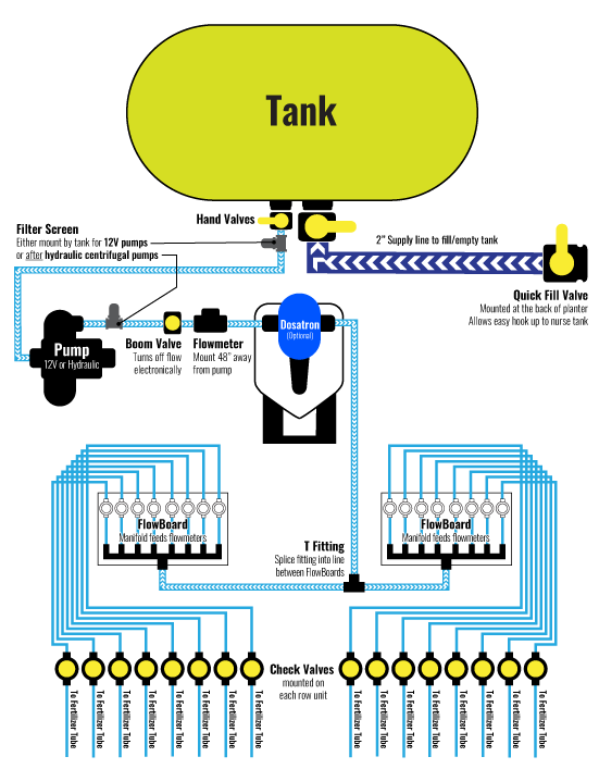
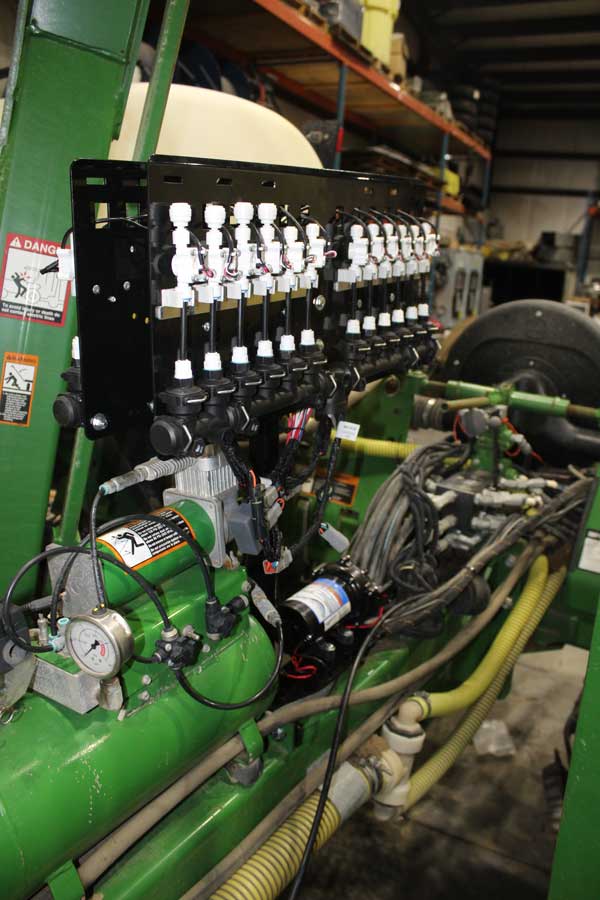
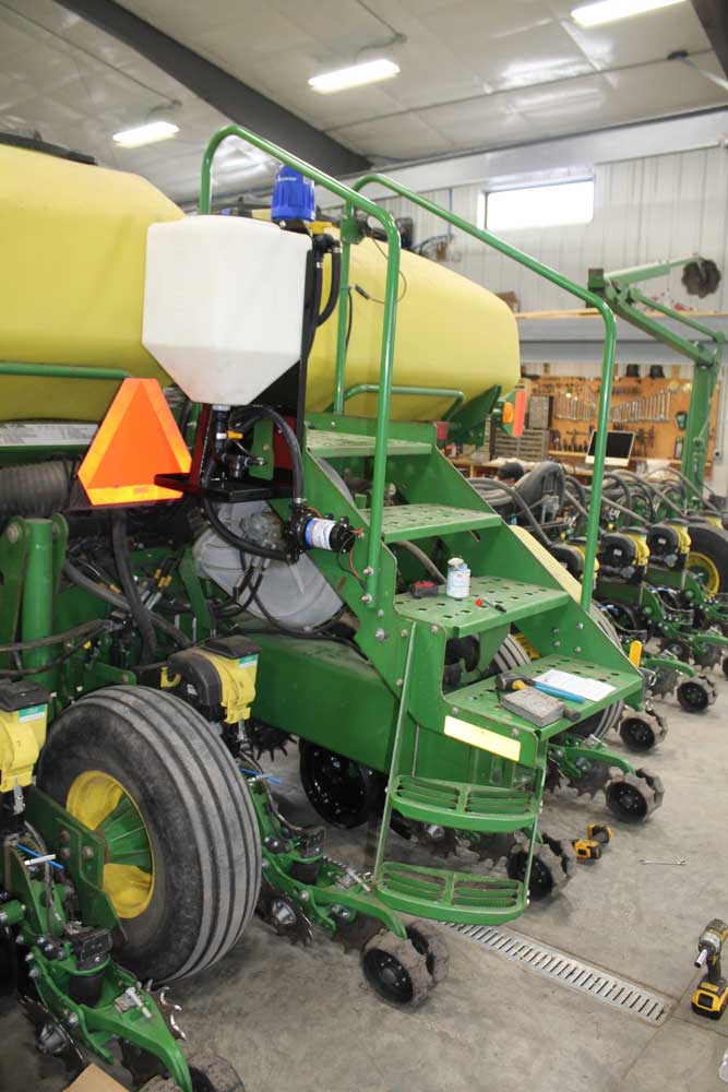
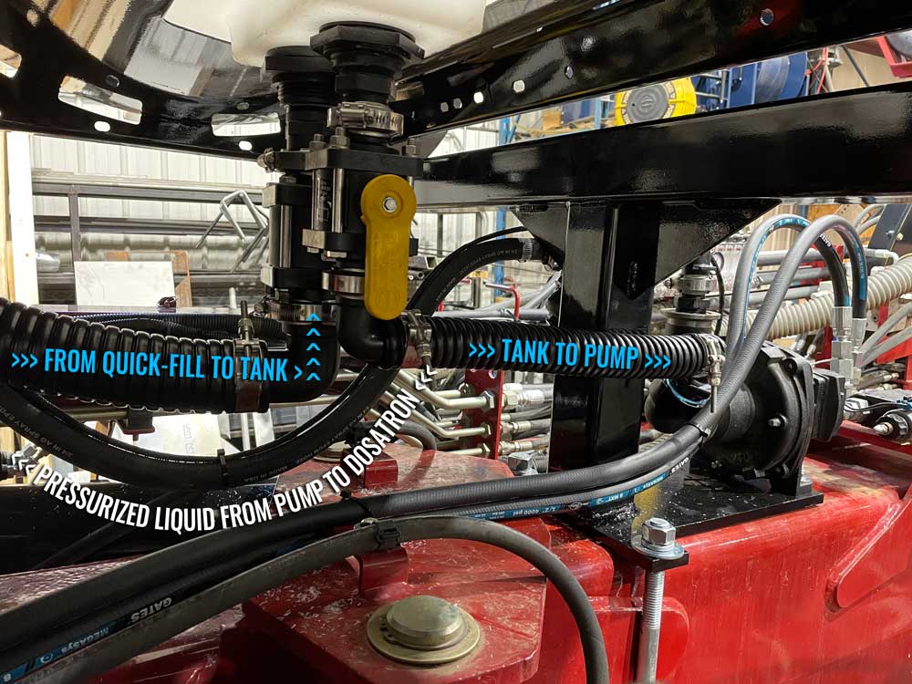
There can be a lot going on in these sections, depending on your setup. It may be as simple as running a hose from the tank to the pump and then running a single line to a flowboard. More likely, we will be dealing with multiple FlowBoards, a Dosatron, and possibly a large flowmeter and a few extra boom valves thrown into the mix.

Don’t worry. Once you know how everything goes together, the plumbing is easy.

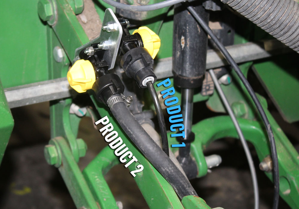
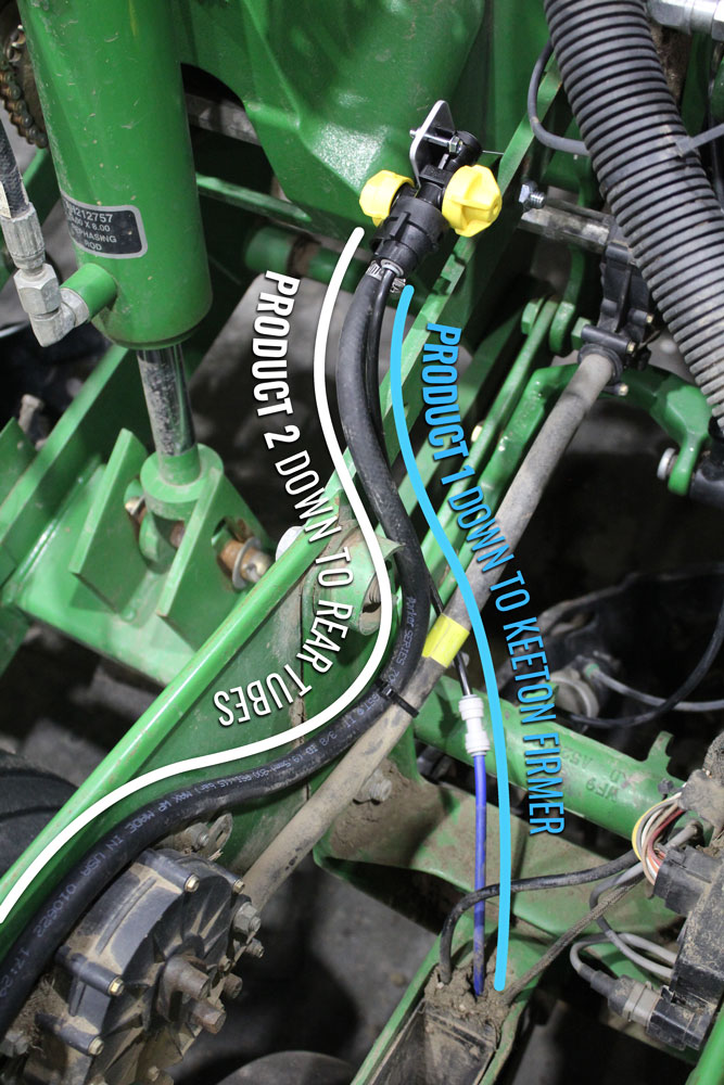
You are going to start by running 2 hoses.

  • The first runs from your leftmost FlowBoard to your rightmost FlowBoard.
  • The second from your pump to the back of your planter. It will likely cross your FlowBoard hose at some point, which will come in handy later.

The Simple Setup

Setting up your Supply Line on a simple system. Usually using a 12V pump

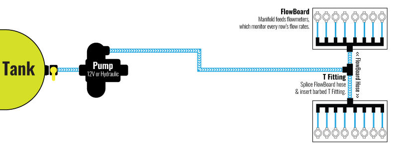
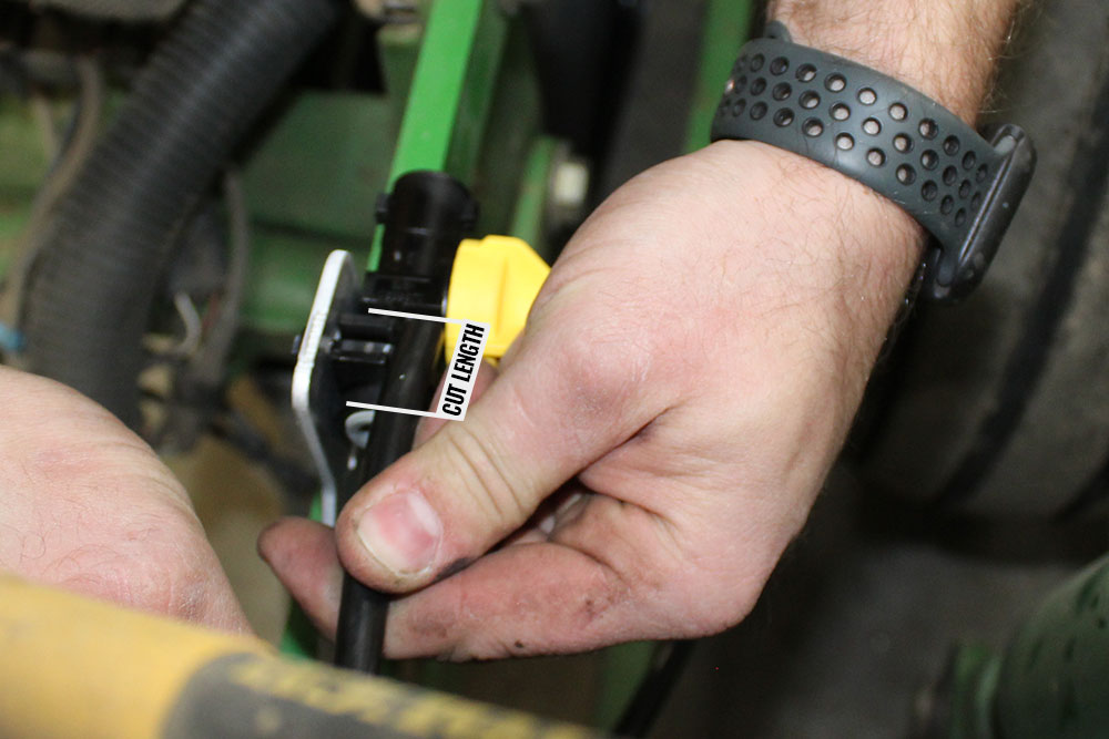
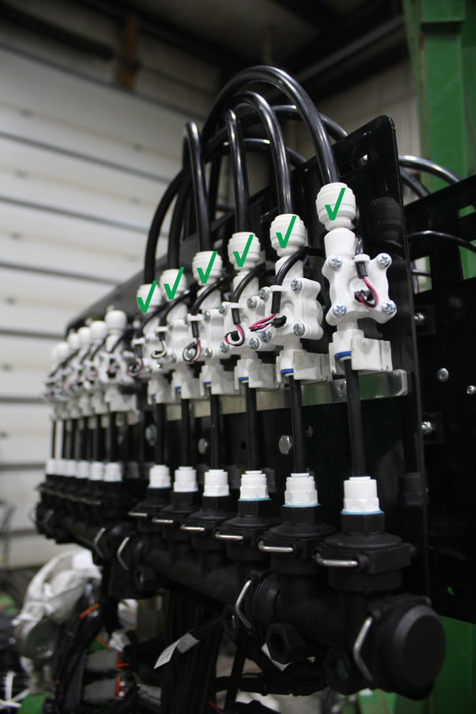
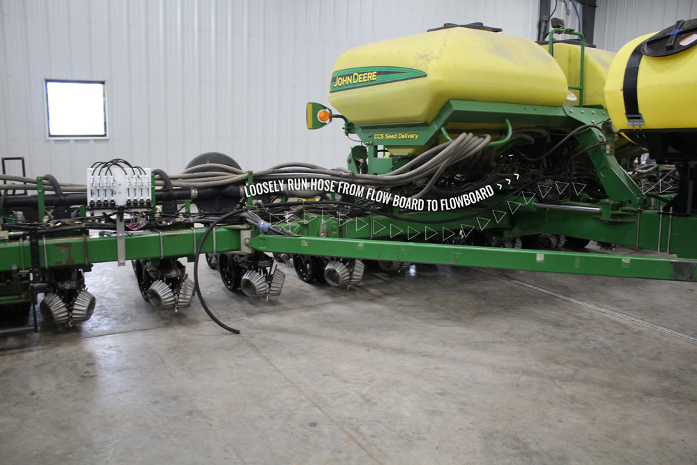
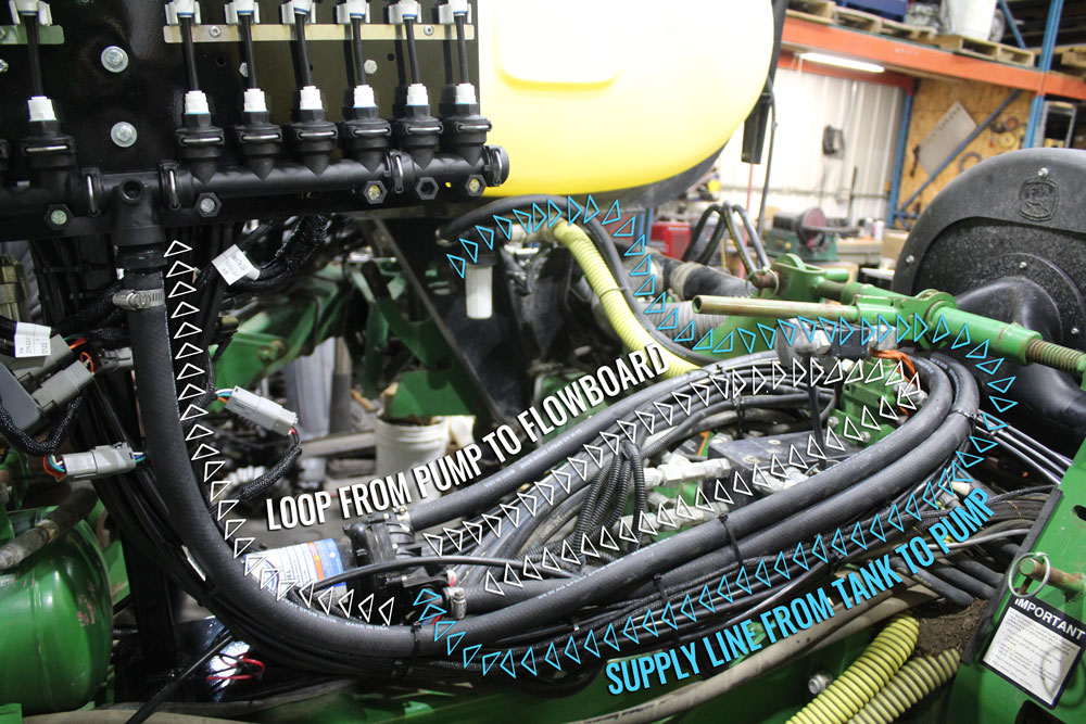
Run your hose from Flowboard to Flowboard (assuming you have at least 2). Make sure to run with existing plumbing wherever possible. Watch for pinch points and leave plenty of slack for the folds. When you are happy with it, secure the hose to the planter using zip ties. Start in the center and work your way to the FlowBoards. Cut the hose and attach each end to the FlowBoard manifolds.

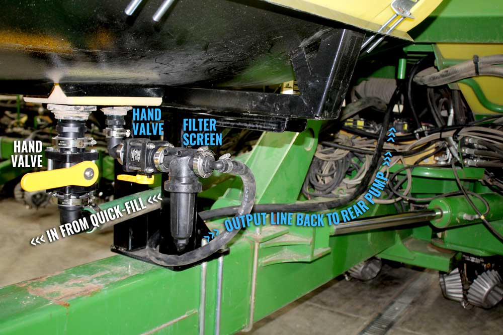
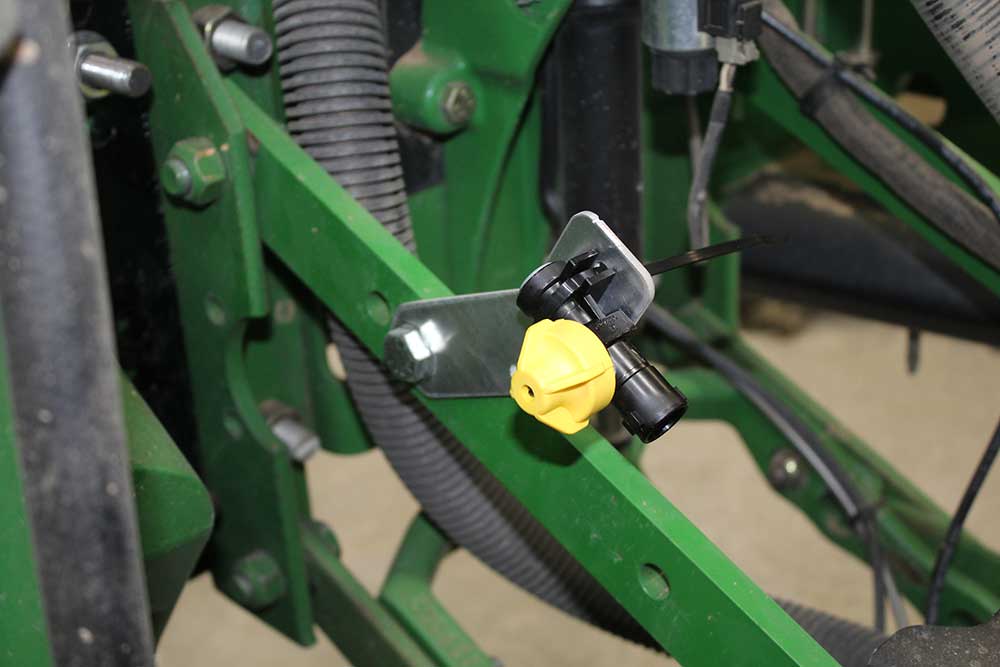
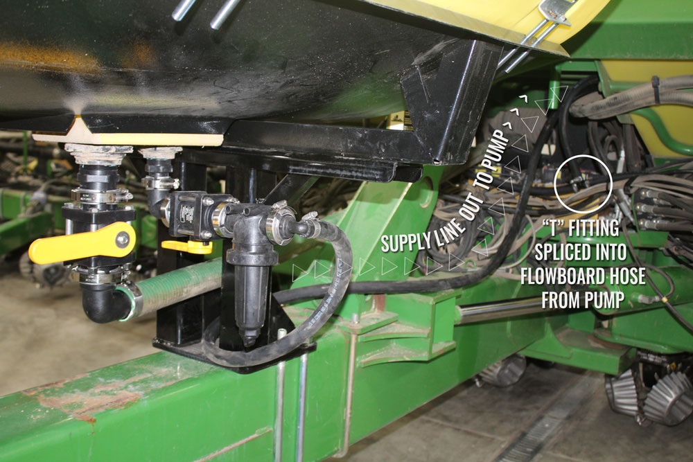
If you are not using a Dosatron, run a hose from your pump to a good intersection point with the FlowBoard hose.  Splice the FlowBoard hose and insert the barbed T fitting. Attach all 3 hose ends to the T. Secure the new hose to the planter where convenient. Cut the hose and attach it to the pump. Done!


The Complex Setup

Complex Supply line with Dosatron product injection, Flowmeter, Boom valve, and more. Usually uses hydraulic pump.

The idea is the same for the complex setup, we just have a few more splices.

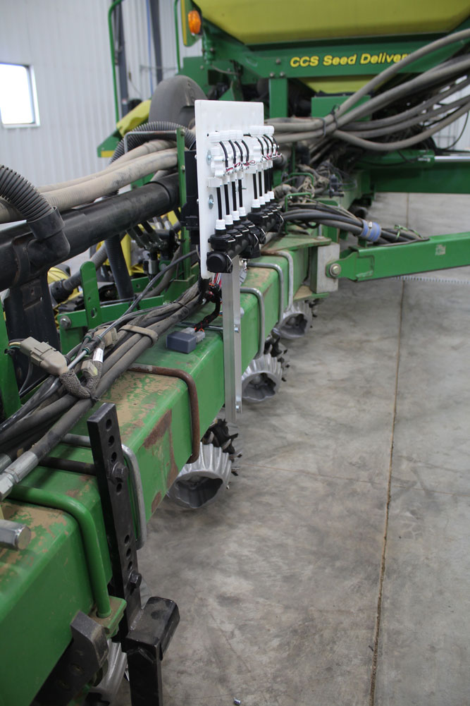
1. Start by running your FlowBoard hose.
Run it from one outside FlowBoard to the other outside FlowBoard. Leave it loose and don’t trim it yet. If you have a 3rd or 4th FlowBoard on this same product to hook in, make sure the hose runs by them as we will splice them into this supply line next. 

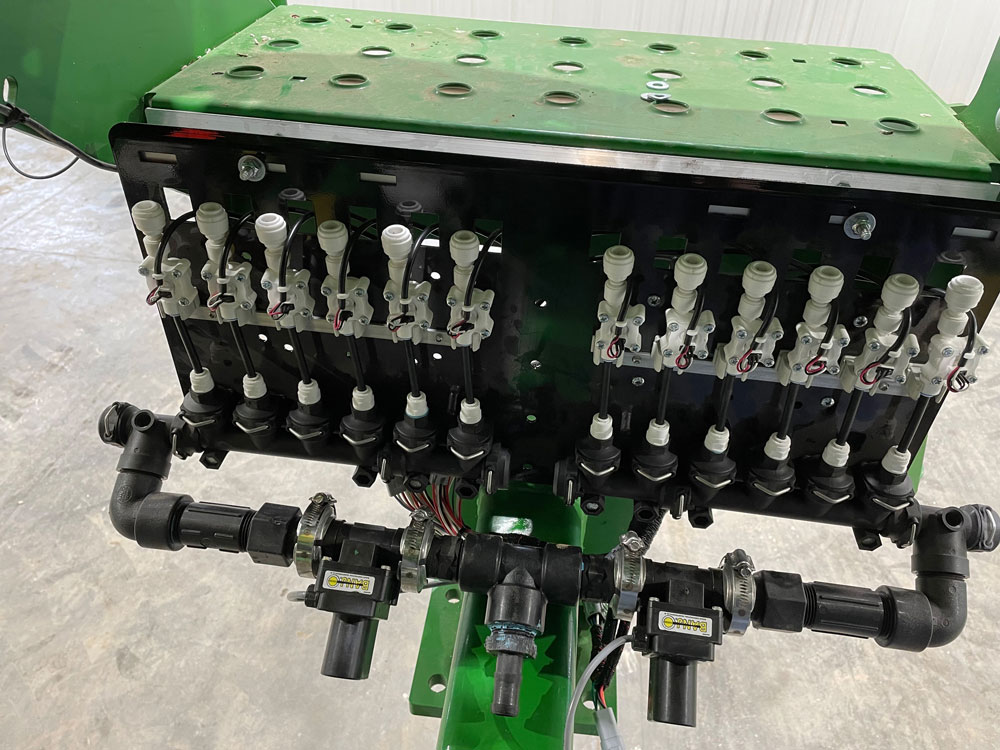
2. Splice in any other FlowBoards and secure the hose to the planter.
We need to splice any additional FlowBoards into the supply hose. Start with the center-most board and work outward. Figure out a good place to splice them into the line, cut the line, insert a barbed T fitting, and run your new T’ed line to the FlowBoard. Repeat as necessary until all the center FlowBoards are plumbed in. 

Now is a good time to secure the FlowBoard hose to the planter, working from the center outward. You should have a pretty good idea of where you’ll T in the supply line from the pump, so leave yourself a little slack there for now. As you get closer to the outside FlowBoards, cut the line to length and attach it to the outside FlowBoards.

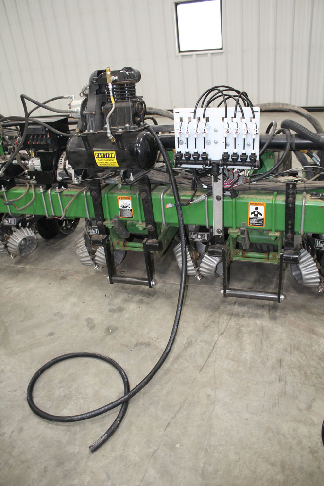
3. Run your pump hose.
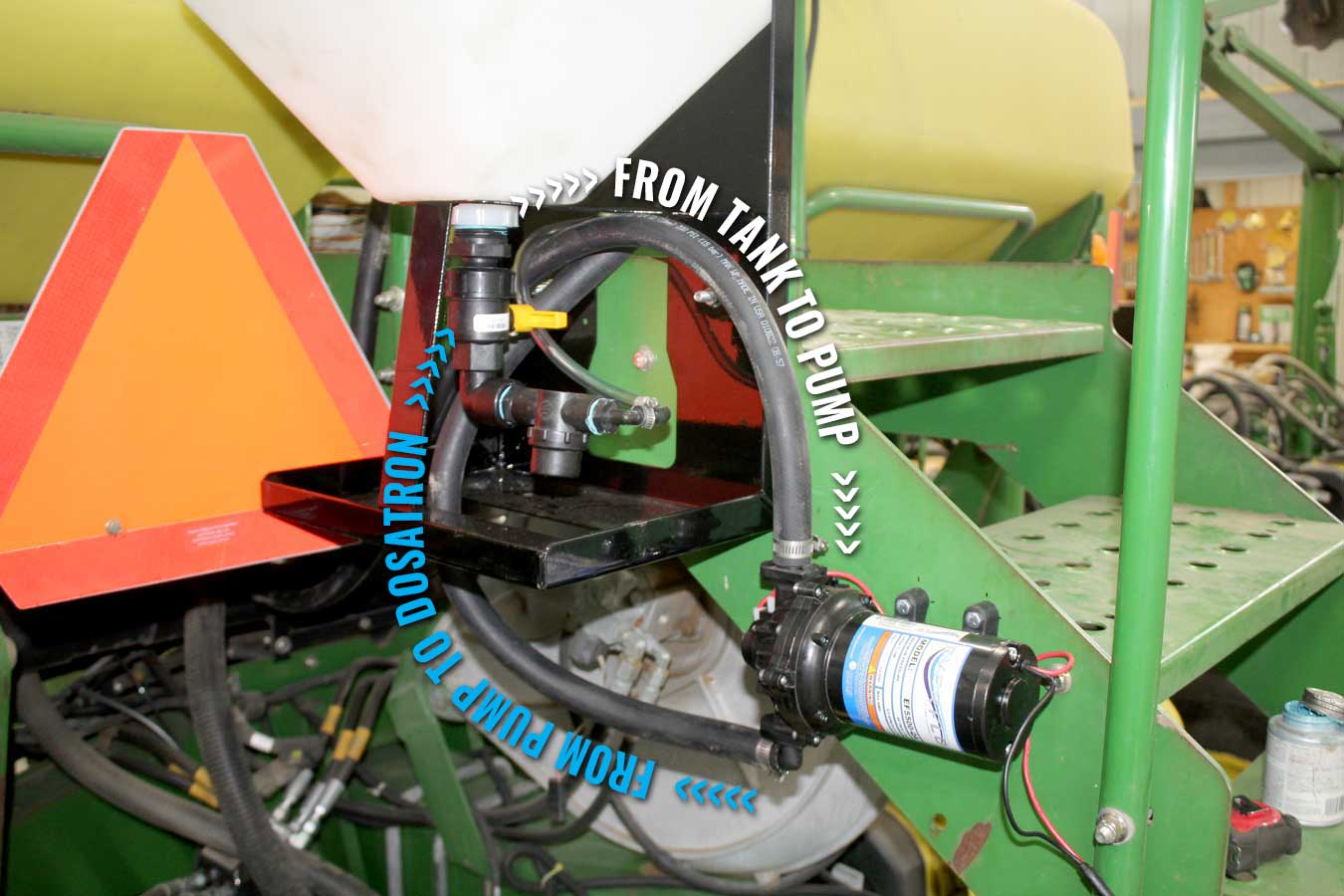
Just like the FlowBoard hose, we will run the pump hose first, then splice in our components in the appropriate places. Route your line loosely all the way back to the Dosatron, usually mounted on the back of the planter. If you are using an electric pump that is mounted near the Dosatron, this hose may actually be the supply line from the tank. 

Either way, you will likely cross the FlowBoard hose somewhere along the way. If you are using a Dosatron, we will trace the return hose back with this supply hose and T into the FlowBoard hose near this intersection. 

4. Add components, starting with the flowmeter
The general order of components

  1. Tank
  2. Pump
  3. Boom Valve/Flowmeter (often fastened together)
  4. Dosatron
  5. T into FlowBoard Supply line
  6. FlowBoards

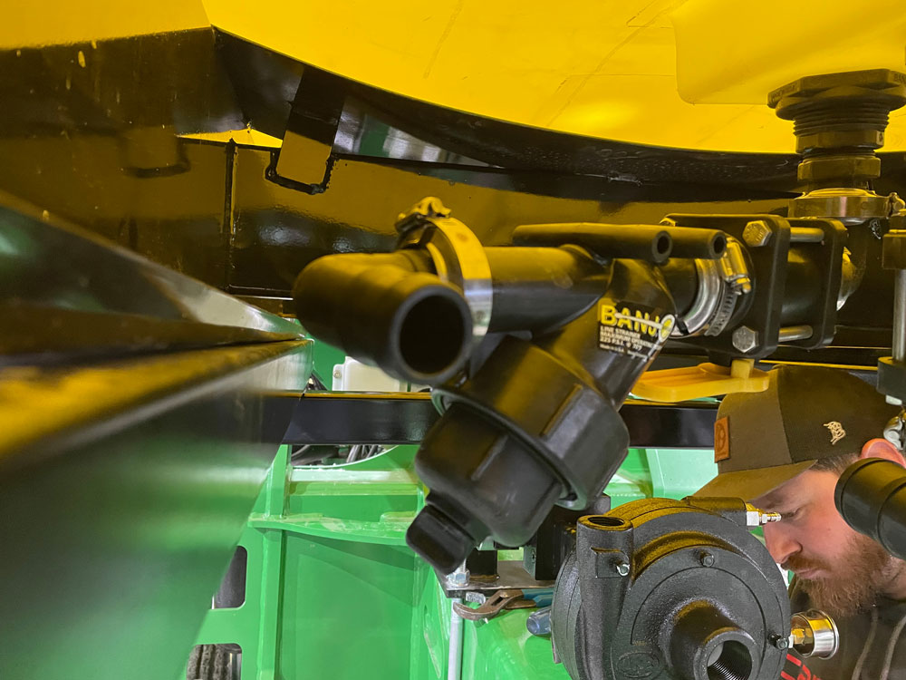
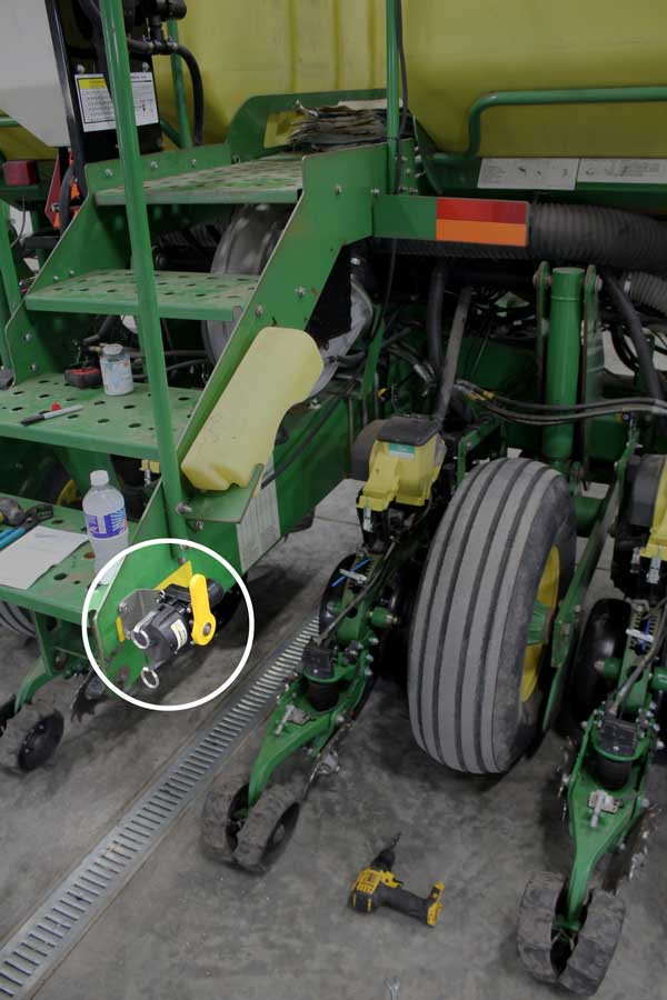
Splice in your flowmeter.
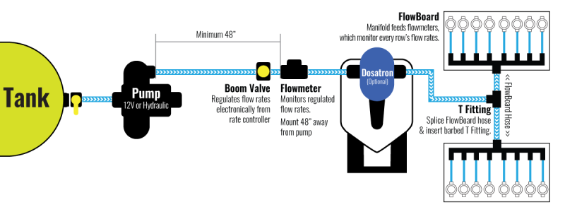
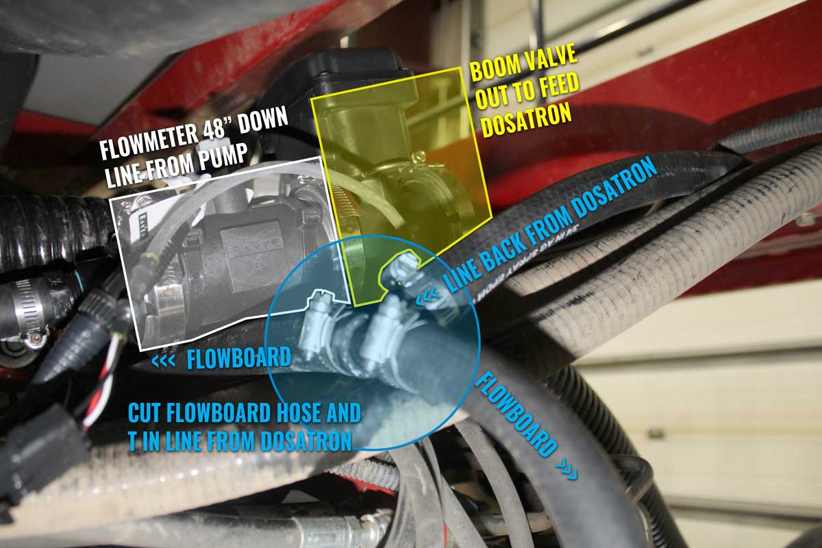
The boom valve & flowmeter are generally plumbed directly to each other, so we can treat them as a single unit. The flowmeter should be mounted after the pump. The most important thing is to keep the flowmeter at least 48″ away from the pump. If you have to coil a hose, do it. If your flowmeter is too close to the pump you will not get accurate readings and it will confuse the rate controller.

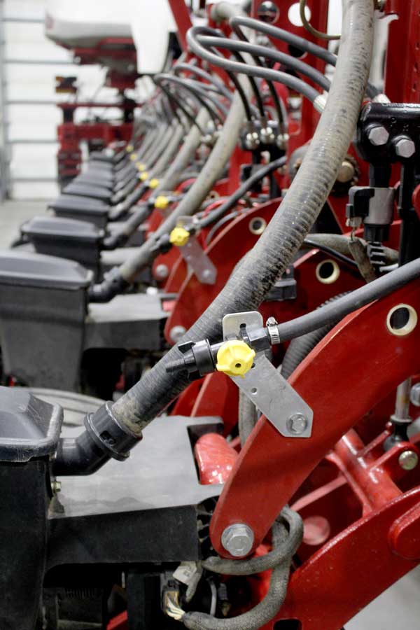
Find a good spot at least 48″ from the pump to plumb in your flowmeter/boom valve combo. Look for someplace that you will be able to secure the assembly out of the way with zip ties. Splice your line, insert the assembly, and secure it to the planter with zip ties.

Secure the line back to the pump, trim the hose as necessary, and attach the hose to the pump. 

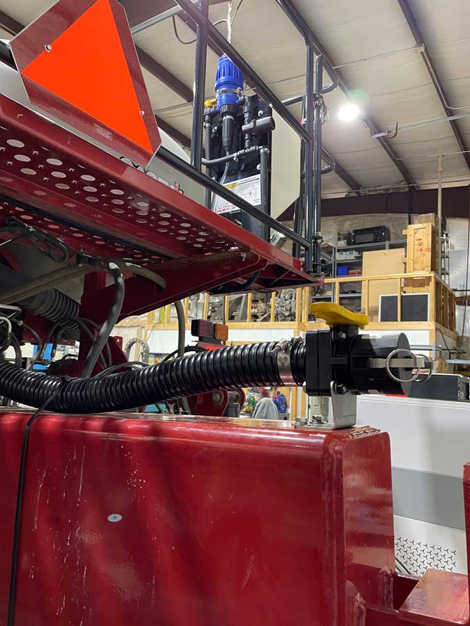
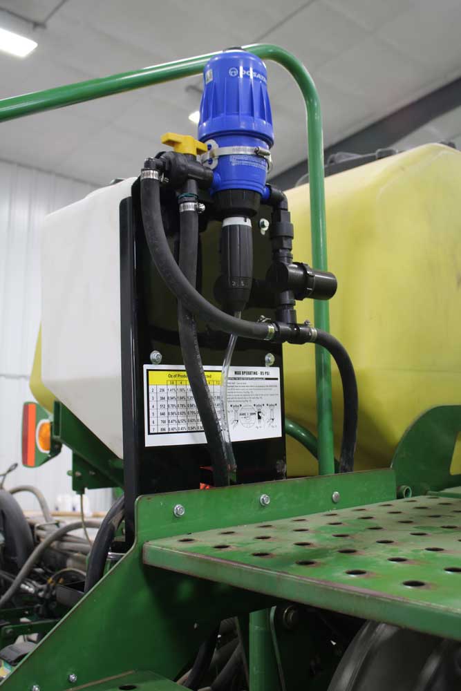
Attach the supply line to the Dosatron 
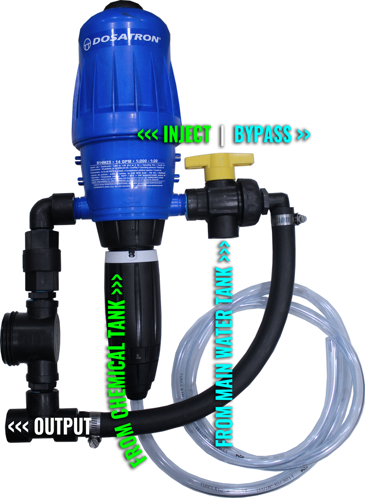
Now that we have our flow rates regulated and monitored, we can plumb in the Dosatron, which will inject the correct amount of product based on this controlled flow rate. 

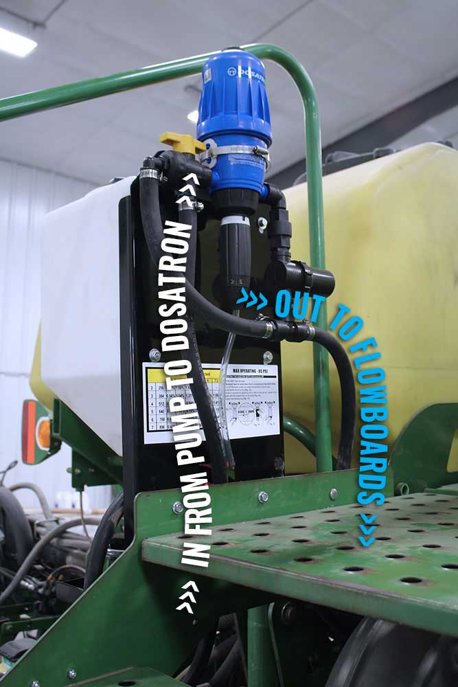
You should pretty much have the hose already routed to the Dosatron, so just secure the line starting at the flowmeter and work your way back. Trim the hose to length and attach it the the supply line. The supply line goes into the 3-way valve on the supply side of the Dosatron. 

Run From the Dosatron back to T into the FlowBoard hose.
Attach your hose the the output of the Dosatron and run the hose back along the supply line you just ran to the intersection with the FlowBoard hose. Secure the two lines together to the planter as you go with zip ties.  

Splice the FlowBoard hose in a good spot and insert your barbed T fitting. Attach all 3 hose ends to the T fitting and secure to the planter with zip ties as necessary. 

Congratulations! You are plumbed all the way up to the tank!  

4: Quick-Fill Valve to Tank

You may decide to do this step first. It is nice to have big line secured to the planter as a guide before you run the tank to pump to Dosatron line.  Realistically, this can be done at anytime once you have both your tank and your quick-fill valve mounted. 

Run the hose straight back through the center of the planter to the quick-fill valve (or vice versa). Secure that end to it’s fitting. 

Important: use a little spray to lubricate both the hose and the fitting (Dakota Shine is our favorite) and attach it to the quick-fill valve. Otherwise you’ll wrestle with the hose for hours. This is good practice on all the barbed hose fittings. 

Secure the hose up out of the way onto the planter, working back to the end that isn’t cut yet. You may have to double up your zip ties to get them long enough to go around both the planter’s frame and this big hose. 

When you feel the hose is secured, trim it to length and attach it to the remaining fitting. Remember to lubricate the fitting and the interior of the hose.  

Congratulations! Your planter is now completely plumbed!

Step 8: Run your hydraulics

If you are running a hydraulic pump or other items, now is a great time to run those lines. Every planter is set up very differently, so use your best judgement when running your hydraulics.  

Be conscious of the heat that can build up in the lines as you run your hose. It is usually best to run all the hydraulic lines together in one bundle and the water hoses & electrical harnesses together in a separate bundle whenever possible. They are going touch at times, just try not to run them together. 


Step 9: Wire the OnSite FMS System

Now that the plumbing is done, it’s usually pretty easy to run your electrical. Most of the time you can just follow your bundle of hoses, securing the wire harness with zip ties directly to the hoses.

If you have excess wire, coil it up and zip tie it out of the way. On the toolbar, the best way to do it is in long loops zip tied at each end. If you are in the center, you can probably coil the wire and stash it with all the other extra wire and hose.

Wiring OnSite FMS
OnSite FMS is designed to be wired in a simple daisy chain configuration. When you turn on the system, it will automatically recognize everything in the system and configure it in the order it was wired together.

The first FlowBoard (rows 1-8 or 1-12) will include your Bluetooth module and your power harness. Each FlowBoard then connects together with module connection harness. The last module in the system will have a terminator plug at the end.

1. Install power and communication harnesses
Let’s start with the first FlowBoard as it has the most going on.

Bluetooth Systems.
Make sure the Bluetooth module is plugged into the flowmeter harness (which should be done for you). Plug the power harness into the other side of the Bluetooth harness and run it to planter power.

When looking for power, you can generally steal it from almost anywhere on the planter, except 12V pumps. A PDM (Power Distribution Module) is always a great choice if you have open circuits. John Deere planters also come with an unused Aux Power connection in the rear of the planter. The OnSite FMS power harnesses should plug into either.

Wired Systems
On wired systems, you will plug the harness that runs to the hitch into the flowmeter harness and run it up the center bar to the hitch on the planter. The harness will provide both power and communication to the system.

2. Run your Module Connection Harnesses
Now that we have communication and power, we just need to share it with the rest of the system. Run the harness from one flowboard to the next. You should be able to follow your supply line, zip tying it to the bundle along the way. As always, watch for pinch points and leave plenty of slack for the folds. Repeat until all the FlowBoards are connected.

3. Install the terminator plug
Add the terminator plug to the last FlowBoard in the series. The terminator plug has a circuit board in it that helps the system figure out how everything is plugged together. The system won’t recognize if the terminator plug isn’t installed. If your system only has one FlowBoard (12 row planters), the terminator plug will still connect to the Flowmeter Harness in place of the Module Connection Harness.

The planter is wired! Now we just need to add the monitor to the cab.

4. Installing the OnSite FMS monitor. 
Installing OnSite FMS in your tractor’s cab is easy. The system comes with an adjustable RAM Mount and a communication cradle.

Attach the RAM Mount where convenient using the supplied hardware. Attach the cradle to the mount. Drop your monitor in the cradle. Done.

5. Run power to the cradle harness. 
Most modern tractors make this very easy and convenient. You can usually find an open power circuit in the cab that will power the system without problems.

Bluetooth System
Simply plug the wires into almost any 12V plug available on the tractor.

Wired System
If you are using a wired system, we recommend using a 30amp circuit to ensure the proper flow of power throughout the system.

6. Install your BENCO Motor Controller (optional)
If you’re running a 12V pump, a motor controller is an incredibly precise (and affordable) way to manage your pressures. It varies the current going to the electric pump very precisely so you can fine tune your application rates in the field from the cab.

  • Mount your BENCO Motor Controller box where it’s convenient.
    You will generally want it close to your OnSite FMS monitor so you can watch how your adjustments affect the application rates in real-time.

  • Hook up the power (red & black wires)
    It doesn’t really matter where the power comes from as long as you are connected to at least a 30Amp circuit. We generally recommend you hook the system directly to the battery. You’ll be powering your pump off of this, so you need plenty of juice to make sure it runs flawlessly.

  • Run power to the pump (green & white wires)
    The green and white wires will run to the power terminals on the pump itself. Green is ground. White is positive.  Extension cables are available if you need them.

  • That’s it! Turn on the system and rotate the knob.
    You should hear your pump speed up and slow down. You can really see the effectiveness of a BENCO motor controller when it’s hooked up to an OnSite Flow Monitoring System.

Congratulations!

You've just installed a full liquid system on your planter.

Translate »